Loading...

Learning

Learning Center

  • Catalog
  • Case Study - UBURR
  • Technical information - UBURR
  • Case Study - UFIBER
  • Technical information - UFIBER

Case Studies

UBURR CASE STUDY #1

Case Study #1 UBURR Industry: Automotive
Objective: Conduct comparison tests against competitors for removing burrs from the front and rear of machined drills.
Application details: Part: Transmission Shaft
Material: AISI 4340, Wr N.1.6928
Pilot Holes: Ø2.5 and Ø3.0mm / .098

READ MORE »
UBURR CASE STUDY #2

Case Study #2 UBURR Industry: Cutting Tools Manufacture
Goal: Removing burrs from reamdrilled drills made for clamping screw
Application details: Material: AISI 4340, Wr N.1.6928 with 45HRc hardness
Pilot Holes: Ø5mm / .197”
Pilot Hole Length: H1=50mm / 1.97”

READ MORE »
UBURR CASE STUDY #3

Case Study #3 UBURR Industry: Medical
Objective: Remove burrs from the front and rear of machined drills for Arthroscopy scissors. The Arthroscopy scissor joint is a reusable system that integrates advanced quality, durability, and precise tactility in each instrument.

READ MORE »
UBURR CASE STUDY #4

Case Study #4 UBURR Industry: General
Objective: Test the UBURR tools on hardened materials and eliminate burrs from the front and rear of machined drills.
Application details: Material: AISI H13, Wr N.1.2344 pallets with 60HRc hardness
Pilot Holes: Ø7mm /

READ MORE »
UBURR CASE STUDY #5

Case Study #5 UBURR Industry: General
Objective: Evaluate the UBURR tools on machined threads and eliminate burrs from both the front and rear of machined drills.
Application details: Material: AISI 4340, Wr N.1.6928 Tool Steel with 38HRc hardness

READ MORE »

Technical Information


How does the UBURR work?

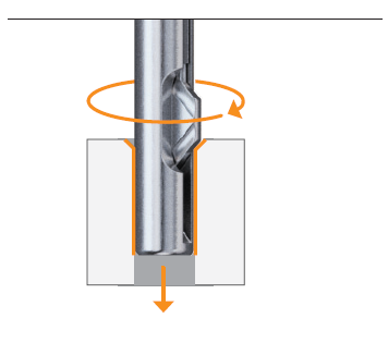
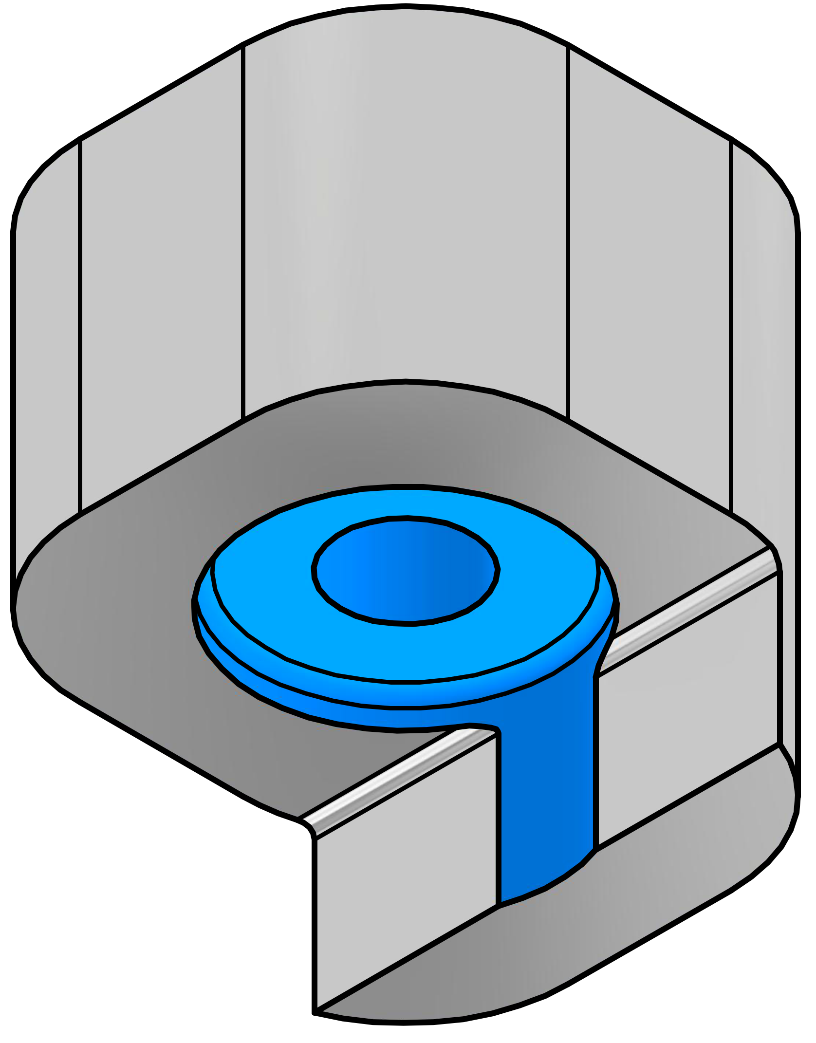
  1. Upon insertion, the replaceable and adjustable cutting blade is initially held in the extended position by spring tension, effectively eliminating the burr on the front side of the hole.
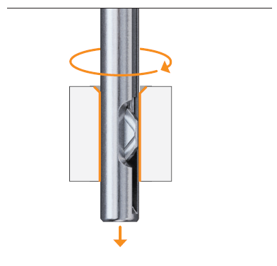
  2. As the cutting tool encounters increased feed pressure, surpassing the preset spring tension, the blade automatically retracts while passing through the pilot-hole. The unique geometry of the blade ensures no marring occurs on the inner surface of the pilot-hole.
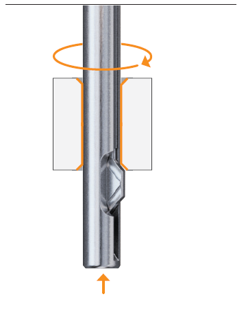
  3. Upon exiting the pilot-hole, spring tension once again triggers the blade to extend, effectively removing the burr on the back side of the hole during the return stroke.
Step 1
Step 2
Step 3

UBURR Blade recommendations

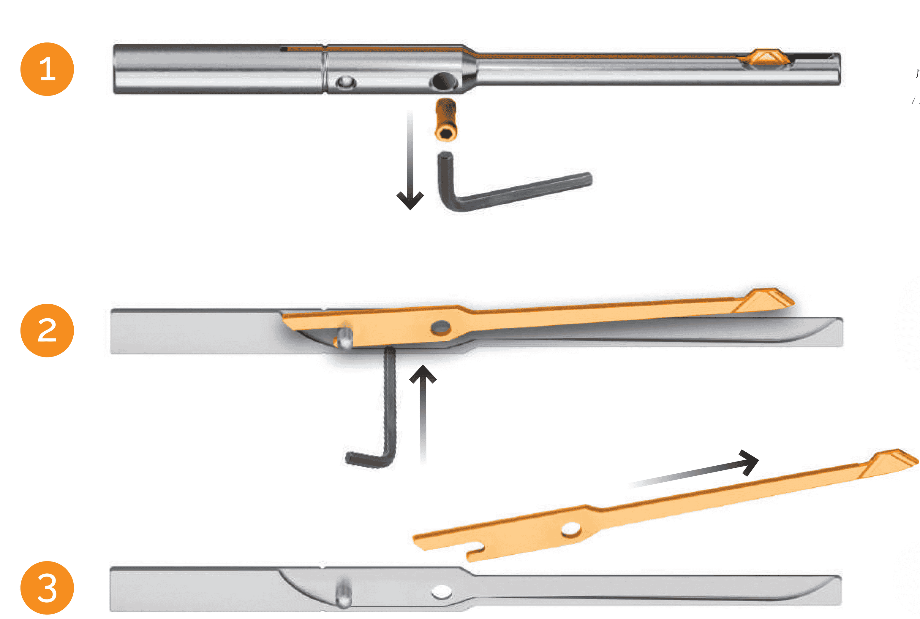
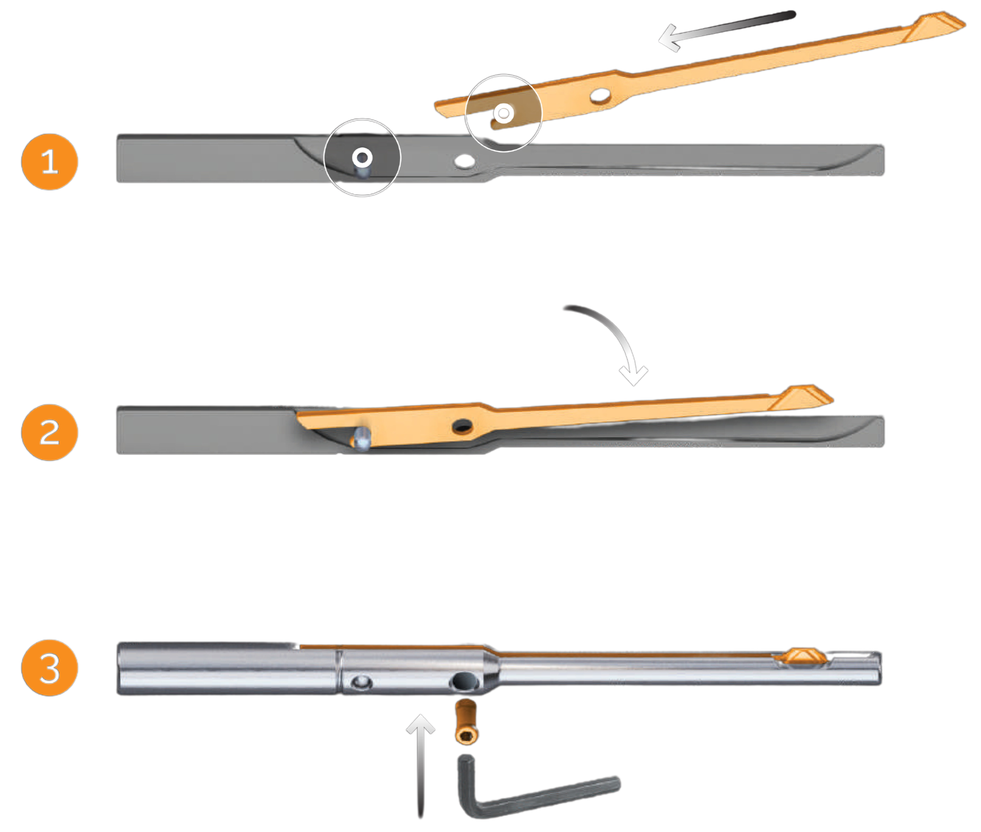
Blade Removal

  1. Remove the blade: Unlock the screw using a 0.05 inch Allen key with a counterclockwise turn of the locking screw.
  2. Push the blade by hexagon key through.
  3. Pull up the blade from the holder.
Blade Removal Steps

Blade Insertion

  1. Insert the blade into the holder slot.
  2. Push the blade into the tool pocket.
  3. Lock the screw clockwise.
Blade Insertion Steps

UBURR cutting recommendations

The table below presents cutting recommendations, outlining initial feed rates and cutting speed for materials group based on ISO 513 and VDI 3323 standards.

(1) To ensure optimal performance and tool-life under varying conditions:

Additionally, the operator must ensure the utilization of appropriate coolant media directed to the cutting tip of the blade and right-hand machining (clockwise).

(1) To ensure optimal performance and tool-life under varying conditions:


Machining guidelines

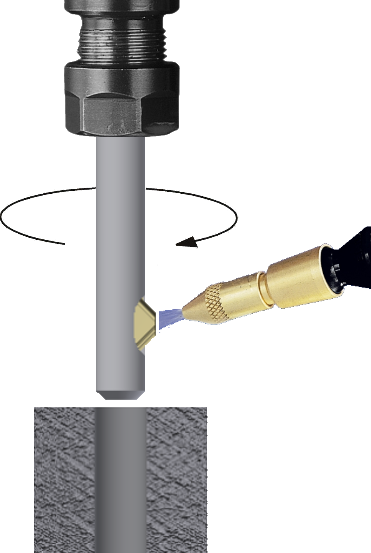
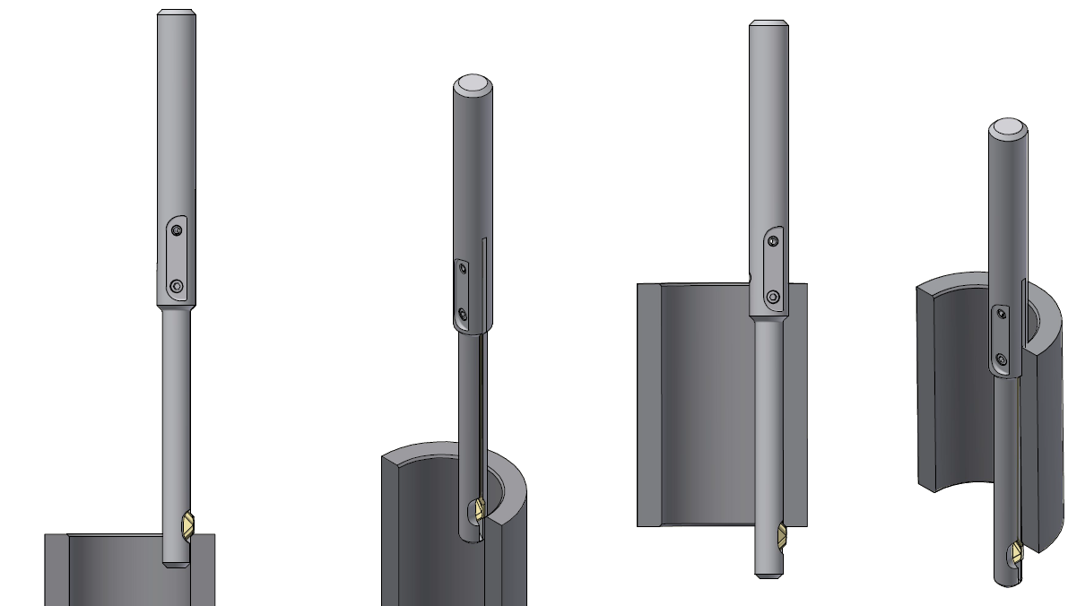
  1. Tool Rotation and Coolant: The UBURR family of tools is suitable for right-hand machining with clockwise tool rotation and should be used with external coolant to flush away chips and swarf from the cutting zone, as shown in Figure 1.
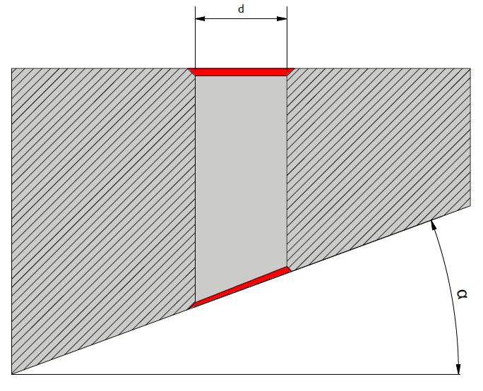
  2. Maximum Slope Angle (α°):
    • For inclined surfaces, as shown in Figure 2, the maximum UBURR operation slope angle depends on the tool-holder diameter. This parameter can be found in the UBURR tool-holders tables parameters under the “Max. Slope Angle” column.
    • For special diameters not listed in the table, please calculate the maximum slope angle using this formula:
    Alpha formula
    • This parameter can be found in the UBURR tool-holders tables parameters under the “Ød range for pilot hole” column with the “min.” value to be considered for “d” in the formula above.
    • For Tubes, as illustrated in Figure 3, it is important to ensure the tool diameter is appropriate for the application according to this formula:
    dtool formula
Figure 1
Figure 1
Figure 2
Figure 2
Figure 3
Figure 3

Using the UUBURR with Electric Hand Drills

UBURR is compatible with both CNC machines and electric hand drills, making it suitable for various operational setups and maximizing the manufacturing process.


Programming guidelines

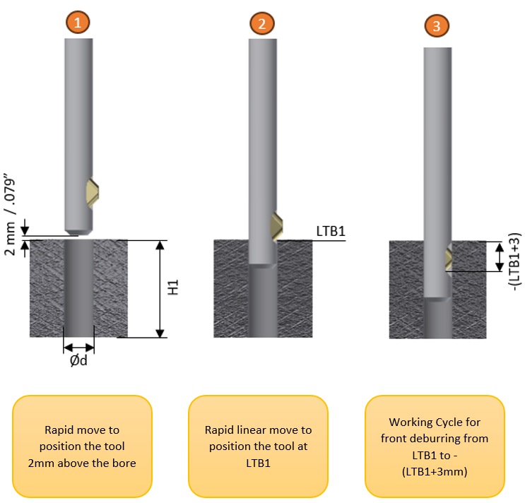
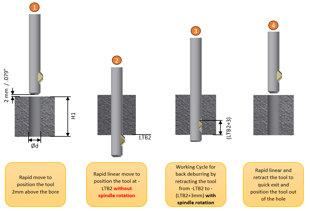
Performing front and back deburring

You can utilize our parametric post routine for milling machines or turning machines to be inserted after each drilling operation:

Front and Back Deburring Steps

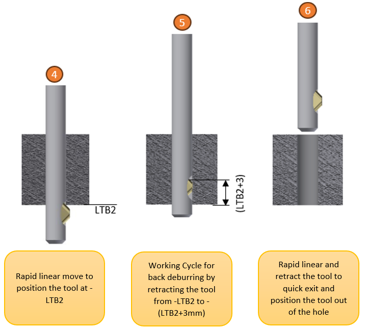
Performing back deburring:

This case involves a different procedure when front deburring is unnecessary.

In such cases, the tool-holder enters the hole without rotating and begins the linear feed only after passing through the pilot hole. Once the tool has passed through the pilot hole, it retracts to execute the back deburring operation.

Performing back deburring process

For performing back deburring, you can also utilize our parametric post for milling machines or turning machines to be inserted after each drilling operation with the same parameters:

  • #101-TOOL LOCATION START
  • #102-S-CUTTING SPEED, ACCORDING TO CUTTING RECOMMENDATIONS
  • #103-H1-PILOT HOLE LENGTH
  • #105-LTB2, ACCORDING TO ITEM TABLE LIST
  • #106-RAPID LINEAR FEED FOR POSITION THE TOOL
  • #107-WORKING CYCLE FEED, ACCORDING TO CUTTING RECOMMENDATIONS

Performing Deburring by Interpolation

UBURR can perform deburring through interpolation, which not only saves on extra tooling costs but also streamlines the production process by integrating multiple functions into one tool.

Front and Back Deburring Steps

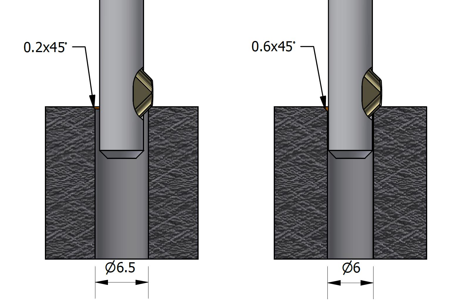
Controlling the chamfer size on the workpiece pilot hole:

Front and Back Deburring Steps

3D Models for UB Sets

3D Models for UB Sets

Case Study UFIBER

UFIBER CASE STUDY #1

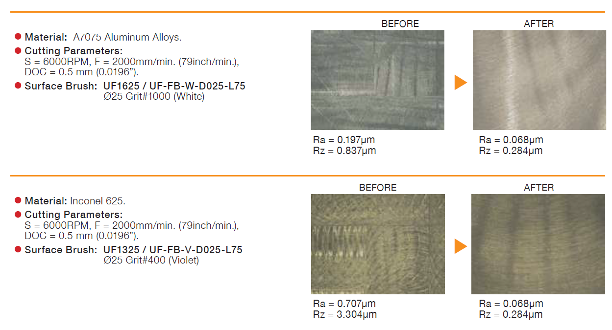
Case Study #1 UFIBER Industry: Aerospace Objective: Eliminate burrs produced during cross-hole drilling on a CNC machine by using the UFIBER surface brush, designed as a cross-hole brush with a tailor-made shank, eliminating the need for manual deburring. Application details:

READ MORE »

Deburring

Burr removal in automotive parts with surface brush

Front and Back Deburring Steps

Burr removal in aerospace parts with surface brush

Front and Back Deburring Steps

Burr removal in pipes with cross-hole brush

Front and Back Deburring Steps

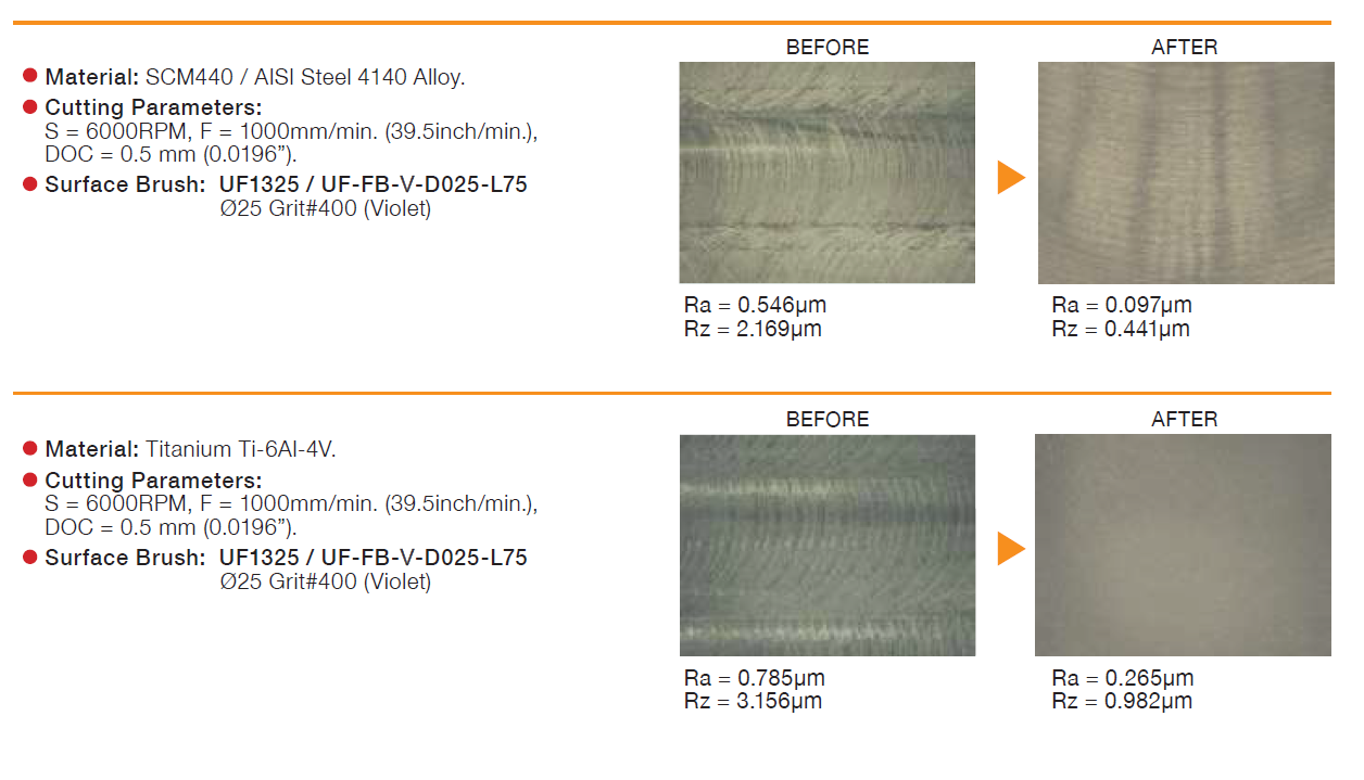
Cutter marks removal with surface brush

Front and Back Deburring Steps

UBACK Technical Guidelines


How does the UBackTool works?

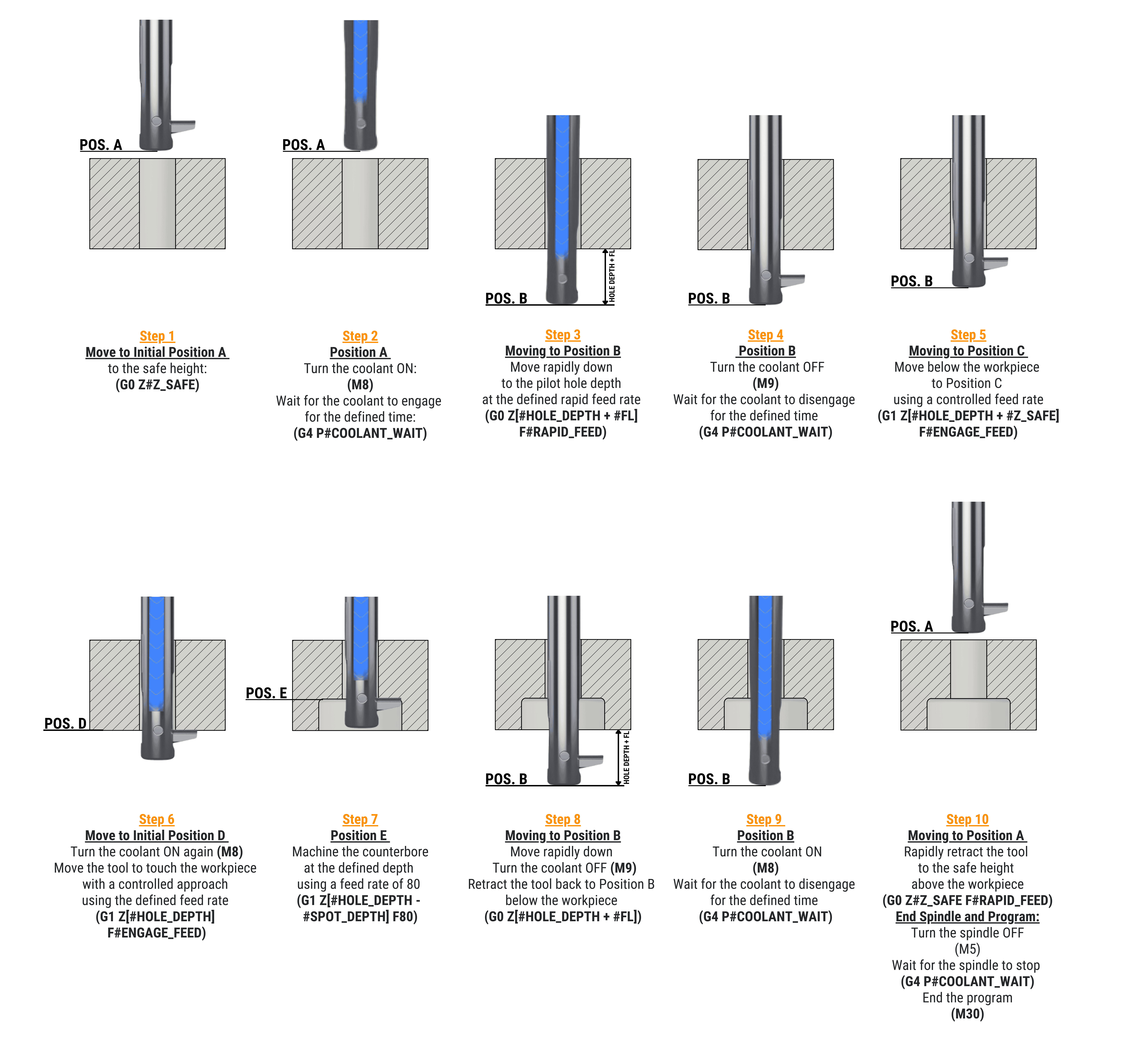
UBack Programming guidelines

Front and Back Deburring Steps
  1. (1) The Folding Length (FL) parameter is listed in the tool-holder tables and is the same for both USPOT inserts and UCHAMF inserts.
  2. (2) The illustrated operation sequence above demonstrates working with a USPOT insert but remains the same when using a UCHAMF insert.

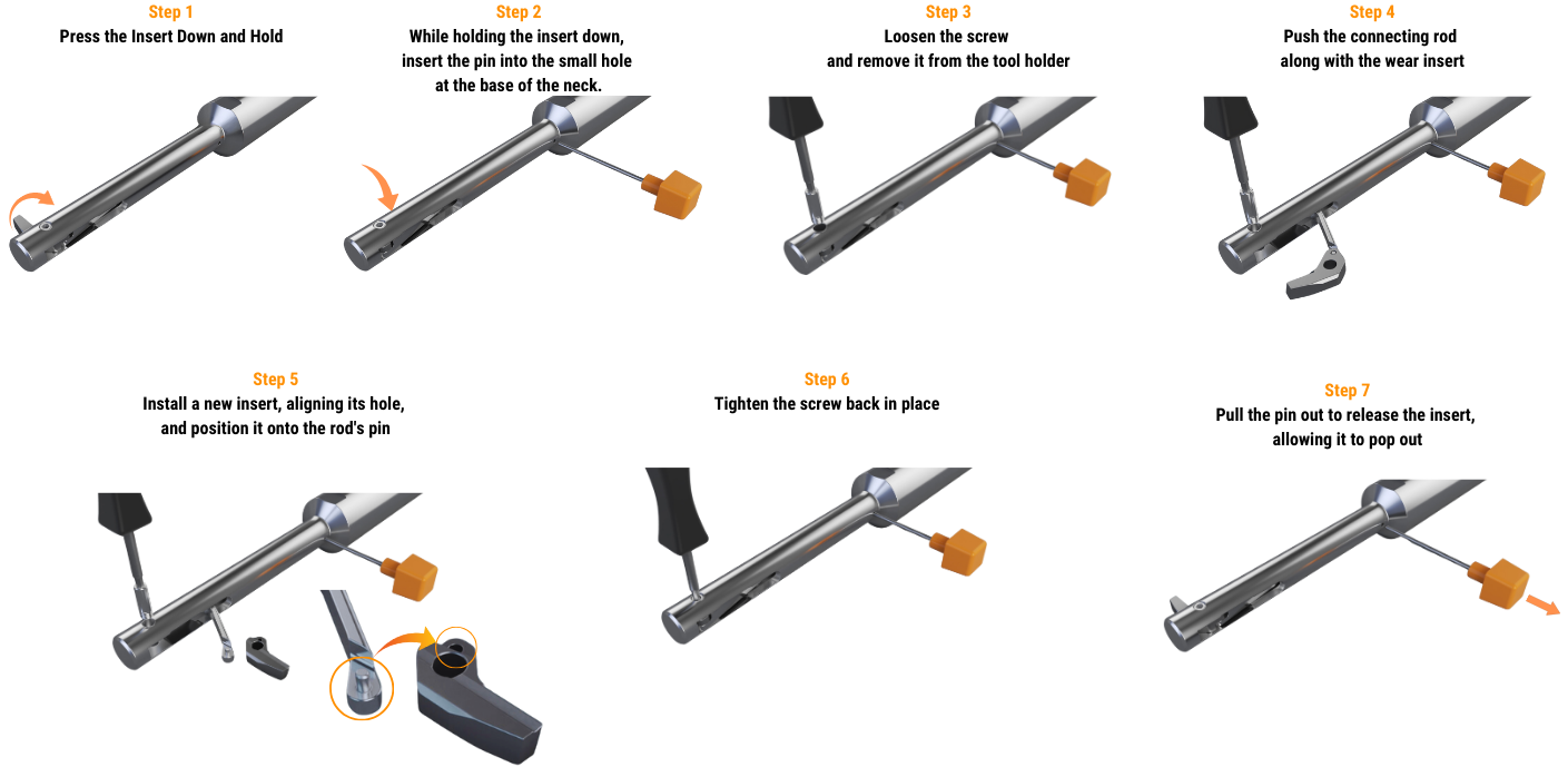
UBack Tool Insert Replacement

Front and Back Deburring Steps

NOTE: The illustrated insert replacement above is demonstrated with a USPOT insert but remains the same when using a UCHAMF insert.

Counterbore Machining Guidelines for Specific Conditions

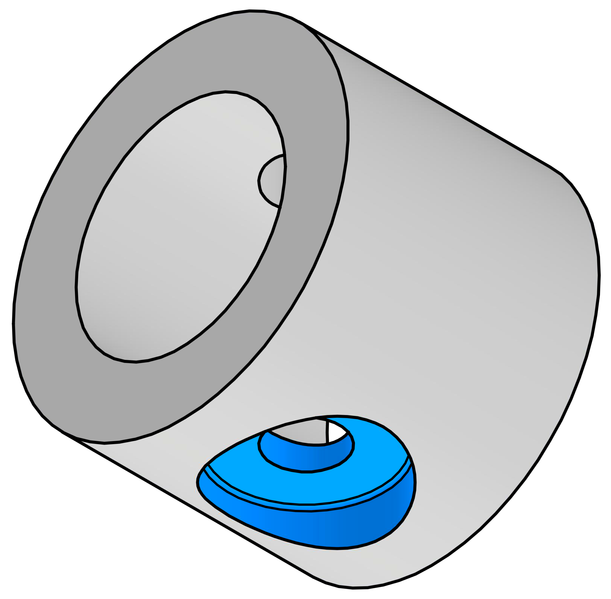
Cylindrical Bore
Counterbore on Cylindrical Bore
  • Use with Internal Coolant
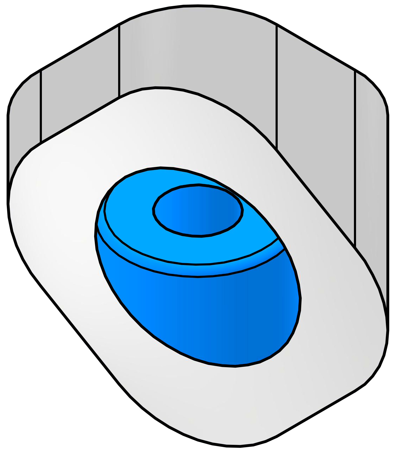
Sloped Surface
Counterbore on Sloped Surface
  • Use external coolant only
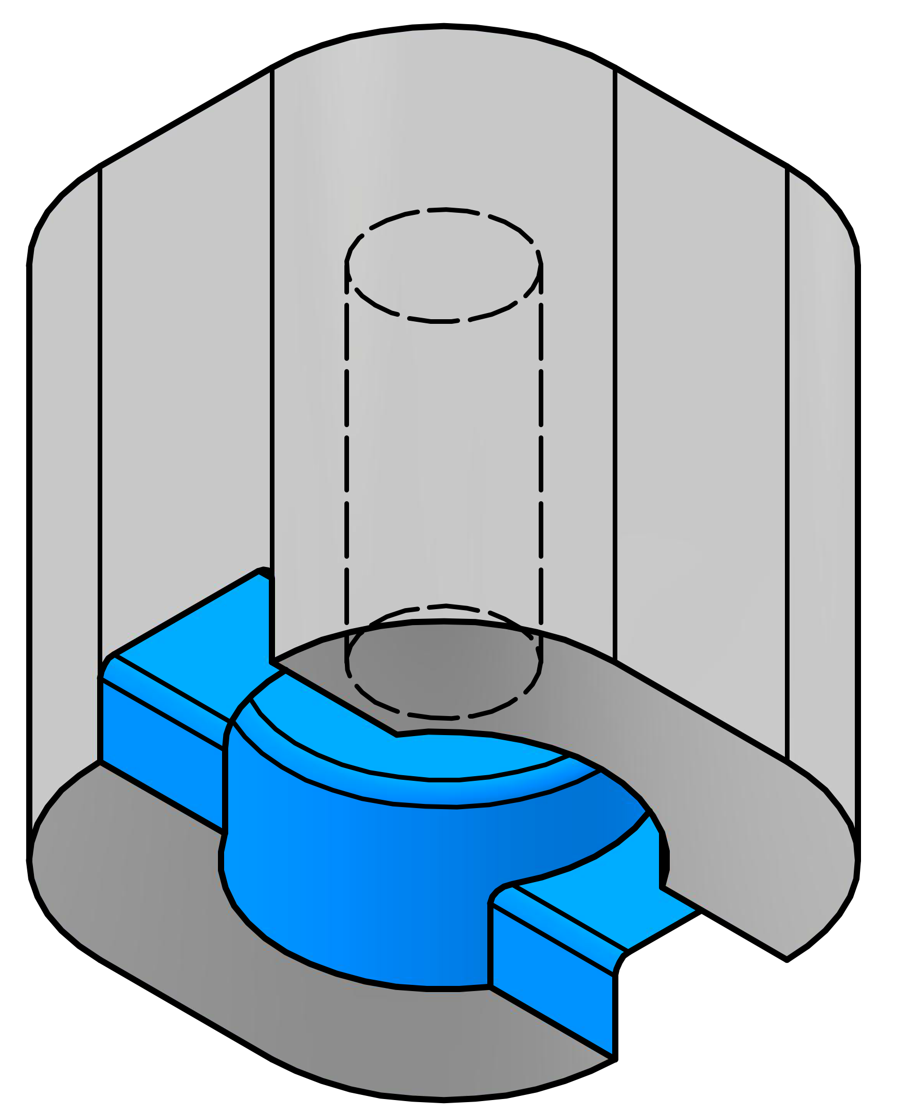
Slot
Counterbore on Slot
  • Fully Interrupted Cut
  • Use external coolant only
  • Consider reduced stability and adjust cutting parameters by reducing them by 30%
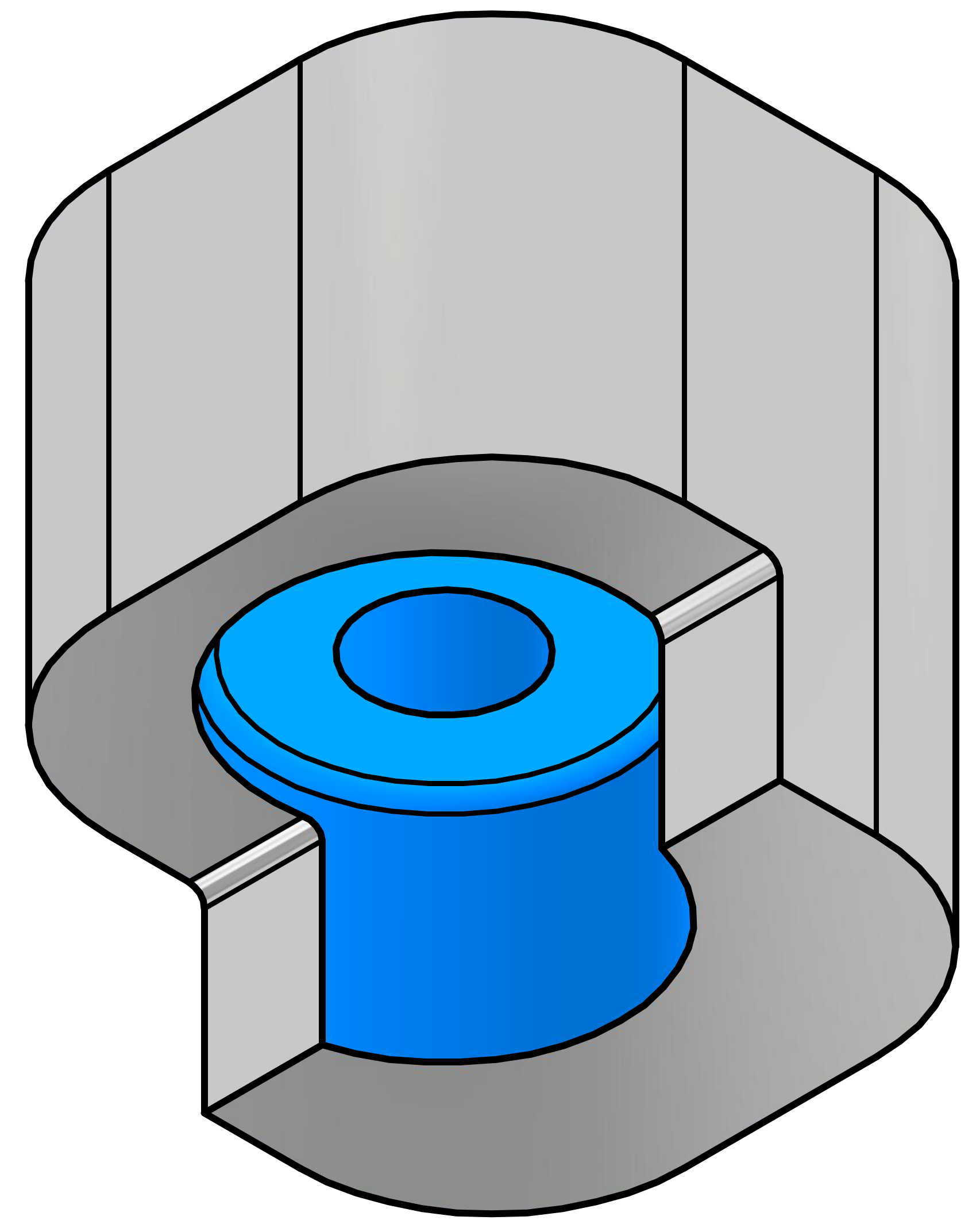
Shoulder
Counterbore on Shoulder
  • Fully Interrupted Cut
  • Use external coolant only
  • Consider reduced stability and adjust cutting parameters by reducing them by 30%
Shoulder 2
Counterbore on Shoulder
  • Fully Interrupted Cut
  • Use external coolant only
  • Consider reduced stability and adjust cutting parameters by reducing them by 30%

Configuring UBACK tool-holders for different cooling systems

UBACK tool-holders are designed for controlling insert retraction using emulsion, air, or Minimum Quantity Lubrication (MQL) coolant systems. When using air or MQL, seal the tool-holder’s coolant inlet with the supplied BR05006 - M5 x 6 mm set screw.

UBACK Tool-holder

UBack Cutting Recommendations

The table below presents cutting recommendations, outlining initial feed rates and cutting speed for materials group based on ISO 513 and VDI 3323 standards.

(1) To ensure optimal performance and tool-life under varying conditions:

Additionally, the operator must ensure the utilization of appropriate coolant media directed to the cutting tip of the blade and right-hand machining (clockwise).

ISO Material Condition As is
AISI / SAE / ASTM
DIN W.-Nr. Vc(1)
cutting
speed
m/min.
/sfm
Series B
ƒr(1)
mm/t
/ipt
Series C
ƒr(1)
mm/t
/ipt
Series D
ƒr(1)
mm/t
/ipt
Series E
ƒr(1)
mm/t
/ipt
Series F
ƒr(1)
mm/t
/ipt
Series G
ƒr(1)
mm/t
/ipt
Recommended
Chip-former
Coolant
P Non-alloy steel
and cast steel,
free cutting
steel
<0.25%
C
Annealed 1020 1.0044 60–120
200–390
0.03
/ 0.0012"
0.04
/ 0.0016"
0.05
/ 0.0020"
0.07
/ 0.0028"
0.08
/ 0.0031"
0.09
/ 0.0035"
PL
/ ML
Air
/ Wet
≥0.25%
C
Annealed 1035 1.0501
< 0.55%
C
Quenched and
tempered
1045 1.1201
≥0.55%
C
Annealed 1055 1.0535
Quenched and
tempered
1060 1.1221
Low alloy
and cast steel,
(less than 5% of alloying
elements)
Annealed G92600 1.5028 50-120
/165-390
0.03
/0.0012″
0.04
/0.0016″
0.05
/0.0020″
0.07
/0.0028″
0.08
/0.0031″
0.09
/0.0035″
Quenched and
tempered
4130 1.7218
4142 1.2332
5045 1.7006 50-100
/165-330
High alloyed steel,
cast steel and tool steel
Annealed H13 1.2344 40-90 /150-295 0.02 /0.0008″ 0.03 /0.0012″ 0.04 /0.0016″ 0.05/0.0020″ 0.06/0.0024″ 0.08 /0.0031″
Quenched and
tempered
M33 1.3249
Stainless steel
and cast steel
Ferritic/martensitic 420 1.4021
Martensitic
M Stainless steel Austenitic, duplex 304L 1.4306 50-100
/165-330
0.03
/0.0012″
0.04
/0.0016″
0.05
/0.0020″
0.07
/0.0028″
0.08
/0.0031″
0.09
/0.0035″
PL Wet
K Gray cast iron (GG) Ferritic / pearlitic Class 25 0.6015 60-120
/200-395
0.03
/0.0012″
0.04
/0.0016″
0.05
/0.0020″
0.07
/0.0028″
0.08
/0.0031″
0.09
/0.0035″
PL Air
/ Wet
Pearlitic / martensitic Grade H20 36037
Nodular cast iron (GGG) Ferritic 60-40-18 0.7043 50-100
/165-330
0.02
/0.0008″
0.03
/0.0012″
0.04
/0.0016″
0.05
/0.0020″
0.06
/0.0024″
0.08
/0.0031″
Pearlitic F33500 0.705
Malleable cast iron Ferritic A47 0.8135
Pearlitic A220 Class 0.8155
N Aluminum-wrought alloys Not hardenable 5005 3.3315 100-16
/330-525
0.05
/0.0020″
0.06
/0.0024″
0.08
/0.0031″
0.10
/0.0039″
0.12
/0.0047″
0.14
/0.0055″
PL Wet
Hardenable 7075 3.4365
Aluminum-cast
alloys
≤12%
Si
Not hardenable 518 3.3292
Hardenable 515 3.3241
>12%
Si
High temperature 390
Copper alloys >1%
Pb
Free cutting C36000 2.0375 90-130
/295-425
Brass C22000 2.023
Electrolytic copper C63000 2.0966
Non metallic Duroplastics, fiber
plastics
Bakelite 180-305
/600-1000
Hard rubber Ebonite
S High temperature alloys Fe
based
Annealed 330 1.4864 40-8
/130-260
0.02
/0.0008″
0.03
/0.0012″
0.04
/0.0016″
0.05
/0.0020″
0.06
/0.0024″
0.08
/0.0031″
PL
ML
Wet
Hardened S590 1.4977
Ni or Co based Annealed Incoloy
825
2.4858 25-40
/80-130
Hardened Inconel
718
2.4668
Cast Nimocast
K24
2.4674
Titanium alloys Pure Titanium
G.1
3.7024 30-60
/100-180
0.02
/0.0008″
0.03
/0.0012″
0.04
/0.0016″
0.05
/0.0020″
0.06
/0.0024″
0.08
/0.0031″
Alpha+beta alloys, hardened Titanium
G.5
3.7165
H Hardened steel Hardened HARDOX
500
30-50
/100-165
0.02
/0.0008″
0.02
/0.0008″
0.03
/0.0012″
0.04
/0.0016
0.05
/0.0020″
0.06
/0.0024″
ML
HL
Air
Hardened HARDOX
Extreme
30-40
/100-130
Chilled cast iron Cast A532 lllA
25% Cr
0.965 45-50
/145-165
0.02
/0.0008″
0.02
/0.0008″
0.03
/0.0012″
0.04
/0.0016
0.05
/0.0020″
0.06
/0.0024″
Cast iron Hardened A532 IID
20%
CrMo
0.9645 30-50
/100-165
0.02
/0.0008″
0.02
/0.0008″
0.03
/0.0012″
0.04
/0.0016
0.05
/0.0020″
0.06
/0.0024″

(1) To ensure optimal performance and tool-life under varying conditions:

Available Coating types and surface treatments:
Coating Key Features Applications Industries Material Examples ISO GROUP
P M K N S H
TiAlN Suitable for mild steels, cast iron, stainless steel, titanium alloys, Inconel, tool steel, and hardened steels. Offers excellent thermal stability, oxidation resistance, and wear resistance. Ideal for high-speed cutting and general-purpose machining. Performs well in both wet and dry conditions. Aerospace, Automotive, General Engineering AISI 304, 42CrMo4, GG (Grey Cast Iron), Ti6Al4V X X
TiAlSiN Provides exceptional hardness and oxidation resistance, withstanding temperatures above 1,200°C. Suitable for high-strength steels, superalloys, hardened steels (over 45 Rc), and titanium alloys. Best for high-performance machining in demanding environments. Excels in dry machining at high speeds. Aerospace, Automotive, Die and Mold Inconel 718, AISI 4140, Ti6Al4V X X X X
AlTiSiN Offers high hardness, thermal stability, and resistance to wear and oxidation. Suitable for stainless steel, hardened cast, superalloys, and steels over 45 Rc. Designed for high-speed machining in extreme conditions. Performs exceptionally in dry machining. Aerospace, Automotive, Precision Engineering AISI 316, AISI H13, Hastelloy X X X X
AlCrN Provides excellent oxidation resistance (up to 1,100°C), toughness, and abrasion resistance. Suitable for carbon steels, cast iron, stainless steel, and aluminum. Suitable for general machining in wet and dry environments. Excels in abrasive and high-wear applications. Automotive, Aerospace, Die and Mold AISI 304, AISI 1045, GG, AL6061 X X X X
AlTiN High hardness, wear resistance, and thermal stability up to 1,100°C. Designed for mild steels, cast iron, high-speed steels, tool steel, and hardened materials. Ideal for heavy-duty machining and high-speed cutting. Performs well in dry and abrasive conditions. Aerospace, Automotive, Heavy Engineering AISI 4340, M2 HSS, GG (Grey Cast Iron) X X X X
TiB2 Known for exceptional chemical stability, low friction, and high thermal conductivity. Best for machining non-ferrous materials such as aluminum, copper, brass, and magnesium alloys. Reduces friction and Built-Up Edge (BUE). Optimized for high-speed machining of non-ferrous metals. Prevents material adhesion and improves efficiency. Aerospace, Automotive, Electronics AL7075, 6061-T6, Copper, Magnesium Alloys (AZ31) X X X X
Polishing Provides a smooth, refined surface finish by removing micro-defects, scratches, or burrs. Enhances aesthetics and surface quality. Reduces friction and BUE. Suitable for machining aluminum with high speeds and high MRR (Metal Removal Rates) Aerospace, Automotive AL7075, 6061-T6, Copper, Magnesium Alloys (AZ31) X X X X X

Chip-formers:

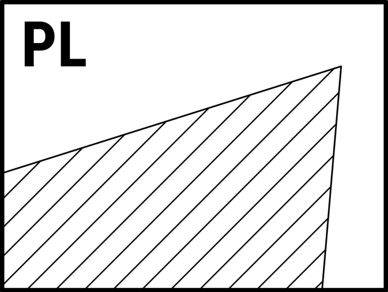
PL

Positive cutting land

Suitable for all around purpose and ISO P,M,K,N,S as well as composite materials

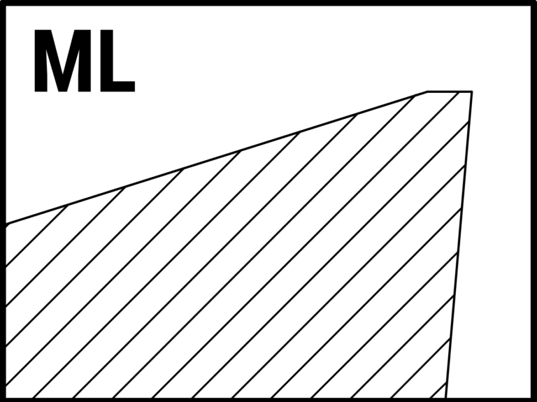
ML

Moderate cutting land

Suitable for ISO P, M, K, S, H materials.

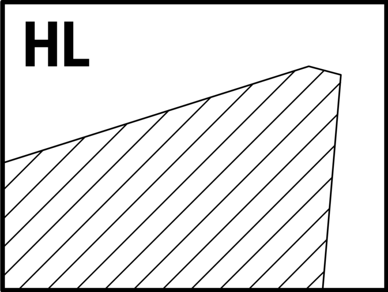
HL

Negative cutting land

Suitable for ISO P, M, K, S, H materials.

Positive cutting land
Moderate cutting land
Negative cutting land