Loading...

UCHAMF

UBACK AND UCHAMF INSERTS

Ultimate Back: Precision Back Counter Solutions

The Ultimate Back line brings together the innovative UX tool-holders and USPOT/UCHAMF inserts to redefine machining precision. Featuring a patented hydraulic mechanism that ingeniously uses the machine’s coolant liquid, this system delivers exceptional control over insert movement. The result? Unparalleled accuracy, repeatability, and streamlined operations for back counterboring, back countersinking, and back spot-facing tasks.

With its advanced engineering, Ultimate Back eliminates the need for workpiece rotation, effortlessly performing operations in a single pass while significantly boosting productivity and efficiency.

Highlights of Ultimate Back

  • UX Tool-Holders with Hydraulic Precision: The UX tool-holders feature a hydraulic mechanism powered by coolant pressure, ensuring smooth, accurate, and repeatable insert movement.
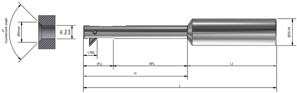
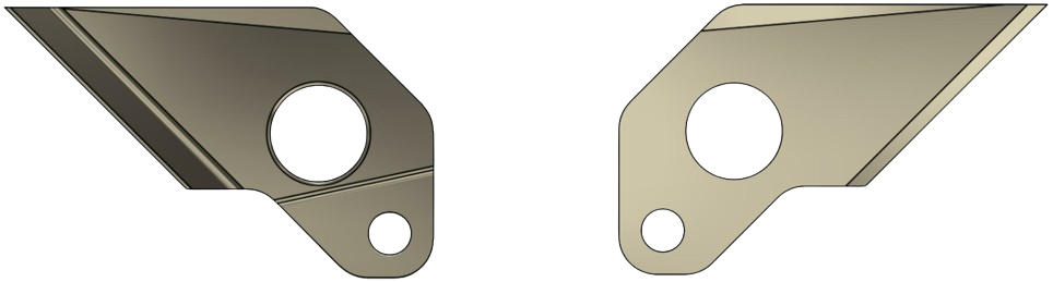
  • USPOT & UCHAMF Inserts: Designed to handle specific machining needs, these inserts deliver outstanding results in back spot-facing, back counterboring, and back countersinking operations.
  • Single-Pass Efficiency: Eliminate workpiece rotation and achieve precise machining in one seamless pass.
  • Industry-Grade Reliability: Engineered to meet the rigorous demands of aerospace, automotive, medical, and electronics industries.
  • Time & Cost Savings: Reduced cycle times and optimized operations ensure significant productivity gains.

Benefits of Ultimate Back

  • Efficient Single Operation: Perform chamfering and counterboring through holes in one pass without rotating the workpiece.
  • Customizable Solutions: UX tool-holders support tailored configurations with USPOT and UCHAMF inserts.
  • Easy Insert Replacement: One type of screw—no special jig required.
  • Superior Chip Management: Excellent chip control for smooth operation.
  • Coolant-Driven Mechanism: Smooth function with internal coolant or air control.
  • Wide Range of Sizes: Available in Ø8 mm to Ø25 mm, with multiple configurations.
Why Ultimate Back Stands Out

The Ultimate Back system combines the precision of UX tool-holders with the versatility of USPOT and UCHAMF inserts to deliver high-performance machining results across demanding industries.

Tool Image 1 Tool Image 2

What is DURASHIELD?

When you see this logo on our tools, you can trust that you’re holding a product built for excellence. DURASHIELD represents NOGA MT’s premium line of tool-holders, engineered to excel in the most demanding environments. Delivering exceptional performance, extended tool life, and unmatched reliability, DURASHIELD tool-holders feature advanced corrosion resistance and superior structural integrity. They set a new benchmark for strength, durability, and precision, redefining industry standards.

MT DURASHIELD Offering:

  • Strength: Ensures tools can withstand heavy loads
  • Toughness: Maintains reliability under demanding conditions
  • Wear Resistance: Extends tool lifespan and reduces costs
  • Machinability: Facilitates the design of precise tool-holders
  • Heat Resistance: Maintains performance at high temperatures
  • Corrosion Resistance: Ideal for harsh environments

The NOGA MT DURASHIELD family of tool-holders undergoes a passivation process to enhance corrosion resistance. This process eliminates the need for additional coatings and chemicals, simplifies production, reduces environmental impact, and provides a more eco-friendly corrosion protection solution.

DURASHIELD Logo

UBACK Series and Range with UCHAMF Inserts for Back Countersink or Chamfering applications:

The UBACK line is organized into series or groups, with each series optimized for a specific pilot-hole range:

Series Ød Pilot-Hole
Range
mm
/ inch
ØD Countersink Range
for 82°
mm
/ inch
ØD Countersink Range
for 90°
mm
/ inch
B 8.0–10.0
/0.315–0.394"
8.5–20.0
/0.335–0.787"
8.5–19.0
/0.335–0.748"
C 11.0–13.0
/0.433–0.512"
11.5–28.0
/0.453–1.102"
11.5–26.0
/0.453–1.024"
D 14.0–16.0
/0.551–0.630"
14.5–34.0
/0.571–1.339"
14.5–31.0
/0.571–1.220"
E 17.0–19.0
/0.669–0.748"
17.5–40.0
/0.689–1.575"
17.5–37.0
/0.689–1.457"
F 20.0–22.0
/0.787–0.866"
20.5–43.0
/0.807–1.693"
20.5–40.0
/0.807–1.575"
G 23.0–25.0
/0.906–0.984"
23.5–46.0
/0.925–1.811"
23.5–43.0
/0.925–1.693"
Countersink Diagram

The UCHAMF inserts are offered as standard (82°, 90° countersink angles) or semi-standard solutions tailored to meet customer-specific applications.

It is mandatory to match the tool-holder series with the corresponding insert series.

UBURR tool-holders metric parameters (mm)

UBURR tool-holder parameters
Ødmin.
Pilot Hole
Tool-
Holder SKU
Tool-Holder
Description
ØDS h6 FL RFC H L L1 LTB2 (1)
UCHAMF
Weight
(gram)
Insert Clamping
Screw
M*P*L (mm)
Series (2)
8 UX2080 UX-d080-B-C16-H62-L115 16 17 43 62 115 53 8.25 69 UX0005
M2.5×0.35×7B
B
9 UX2090 UX-d090-B-C16-H62-L115 16 17.8 43 62 115 53 8.25 76 B
10 UX2100 UX-d100-B-C16-H62-L115 16 18.4 43 62 115 53 8.25 82 B
11 UX3110 UX-d110-C-C16-H80-L133 16 27 52 80 133 53 13.6 93 UX0006
M3×0.35×10C
C
12 UX3120 UX-d120-C-C16-H80-L133 16 27.3 52 80 133 53 13.6 103 C
13 UX3130 UX-d130-C-C16-H80-L133 16 28 52 80 133 53 13.6 115 C
14 UX4140 UX-d140-D-C20-H105-L158 20 32.5 72.5 105 158 53 15.3 160 UX0007
M3×0.35×13D
D
15 UX4150 UX-d150-D-C20-H105-L158 20 32.5 72.5 105 158 53 15.3 178 D
16 UX4160 UX-d160-D-C20-H105-L158 20 32.5 72.5 105 158 53 15.3 196 D
17 UX7200 UX-d200-G-C25-H120-L175 20 38.5 76.5 115 170 55 18 231 UX0008
M3x0.35x16E
E
18 UX7200 UX-d200-G-C25-H120-L175 20 38.5 76.5 115 170 55 18 254 E
19 UX7200 UX-d200-G-C25-H120-L175 20 38.5 76.5 115 170 55 18 278 E
20 UX7200 UX-d200-G-C25-H120-L175 25 43.5 76.5 120 175 55 20 344 UX0009
M4x0.5x19F
F
21 UX7210 UX-d210-G-C25-H120-L175 25 43.5 76.5 120 175 55 20 373 F
22 UX7220 UX-d220-G-C25-H120-L175 25 43.5 76.5 120 175 55 20 403 F
23 UX7230 UX-d230-G-C25-H120-L175 25 48 72 120 175 55 22 427 UX0010
M4x0.5x21G
G
24 UX7240 UX-d240-G-C25-H120-L175 25 48 72 120 175 55 22 445 G
25 UX7250 UX-d250-G-C25-H120-L175 25 48 72 120 175 55 22 492 G

(1) The LTB parameter varies between USPOT and UCHAMF inserts

(2) The insert series must match the series of the tool holder.

Note: Tool-holders and inserts are sold separately.

UX Tool-holders spare parts:
  • 🔧 SP0105 Hex L-Key 0.050" 1+1/16/1+9/16
  • 🔩 UX0003 Pin for Insert Replacement
  • 🪛 Insert Clamping Screw – according to the table above

UBACK Standard Tool-Holders with UCHAMF Inserts(Imperial)

UBURR tool-holder parameters
Ødmin.
Pilot Hole
Tool-
Holder SKU
Tool-Holder
Description
ØDS h6 FL RFC H L L1 LTB2 (1)
UCHAMF
Weight
(lBs)
Insert Clamping Screw
M*P*L
(mm)
Series(2)
0.315 UX2080 UX-d080-B-C16-H62-L115 0.630 0.669 1.693 2.441 4.528 2.087 0.325 0.1521 UX0005
M2.5×0.35x7B
B
0.354 UX2090 UX-d090-B-C16-H62-L115 0.630 0.701 1.693 2.441 4.528 2.087 0.325 0.1676 B
0.394 UX2100 UX-d090-B-C16-H62-L115 0.630 0.740 1.693 2.441 4.528 2.087 0.325 0.1808 B
0.433 UX3110 UX-d110-C-C16-H80-L133 0.630 1.063 2.047 3.150 5.236 2.087 0.535 0.205 UX0006
M3x0.35x10C
C
0.472 UX3120 UX-d110-C-C16-H80-L133 0.630 1.075 2.047 3.150 5.236 2.087 0.535 0.2271 C
0.512 UX3130 UX-d110-C-C16-H80-L133 0.630 1.102 2.047 3.150 5.236 2.087 0.535 0.2535 C
0.551 UX4140 UX-d140-D-C20-H105-L158 0.787 1.280 2.854 4.134 6.220 2.087 0.602 0.3527 UX0007
M3x0.35x13D
D
0.591 UX4150 UX-d150-D-C20-H105-L158 0.787 1.280 2.854 4.134 6.220 2.087 0.602 0.3924 D
0.630 UX4160 UX-d140-D-C20-H105-L158 0.787 1.280 2.854 4.134 6.220 2.087 0.602 0.4321 D
0.669 UX4170 UX-d170-E-C20-H115-L170 0.787 1.516 3.012 4.528 6.693 2.165 0.709 0.5093 UX0008
M3x0.35x16E
E
0.709 UX4180 UX-d180-E-C20-H115-L170 0.787 1.516 3.012 4.528 6.693 2.165 0.709 0.56 E
0.748 UX4190 UX-d190-E-C20-H115-L170 0.787 1.516 3.012 4.528 6.693 2.165 0.709 0.6129 E
0.669 UX4200 UX-d200-F-C25-H120-L175 0.984 1.713 3.012 4.724 6.890 2.165 0.787 0.7584 UX0009
M4x0.5x19F
F
0.827 UX4210 UX-d210-F-C25-H120-L175 0.984 1.713 3.012 4.724 6.890 2.165 0.787 0.8223 F
0.866 UX6220 UX-d220-F-C25-H120-L175 0.984 1.713 3.012 4.724 6.890 2.165 0.787 0.8885 F
0.906 UX4230 UX-d230-F-C25-H120-L175 0.984 1.890 2.835 4.724 6.890 2.165 0.866 0.9414 UX0010
M4x0.5x21G
G
0.945 UX4240 UX-d240-F-C25-H120-L175 0.984 1.890 2.835 4.724 6.890 2.165 0.866 0.9811 G
0.984 UX4250 UX-d250-F-C25-H120-L175 0.984 1.890 2.835 4.724 6.890 2.165 0.866 1.0847 G

(1) The LTB parameter varies between USPOT and UCHAMF inserts

(2) The insert series must match the series of the tool holder.

Note: Tool-holders and inserts are sold separately.

UX Tool-holders spare parts:
  • 🔧 SP0105 Hex L-Key 0.050" 1+1/16/1+9/16
  • 🔩 UX0003 Pin for Insert Replacement
  • 🪛 Insert Clamping Screw – according to the table above

UBACK tool-holders coding system specifications and identification:

UBACK coding system diagram
Ordering special UBack Tool-holders

We can also modify or produce tailor-made tool-holders.

If you need further assistance, please don’t hesitate to contact us.

Providing an application drawing or sketch, the raw material details, and any other relevant information will help us assist you more effectively.

How to Select the Correct Tool-Holder and UCHAMF Insert to Match Your Application:

For Standard Inserts:
  • Refer to the “UCHAMF 82° and 90° Standard Inserts (mm/inch)” table below.
  • Standard inserts are available for 82° and 90° countersink angles.
For Semi-Standard Solutions:
  1. Select the appropriate tool-holder based on the pilot hole diameter.
    For example, if the pilot hole diameter is 8.5 mm, choose the UX2080, which supports a minimum diameter (Ødmin) of 8 mm.
  2. Define the required parameters for the UCHAMF insert, including the countersink angle, chip-former, and coating.
  3. Complete the relevant details for the UCHAMF insert description according to the specifications provided below.
  4. Ensure compatibility between the UCHAMF insert series and the corresponding UX tool-holder. The series of the insert must align with the series of the tool-holder.
Notes:
  1. Coating – Our top recommendation is the NCT grade, featuring the versatile TiAlN PVD coating. It offers excellent thermal stability, oxidation resistance, and is compatible with a wide range of materials, including mild steels, stainless steel, and Inconel.For additional options, refer to the list of available coatings below.
  2. Tool-holders and inserts are sold separately.

UCHAMF Inserts Coding System Specifications and Identification

UCHAMF Insert Image 1
UCHAMF Insert Image 2

UCHAMF 82° and 90° Standard Inserts (mm/inch)

Ødmin.
Pilot Hole
mm/inch
Countersunk angle α=82° Countersunk angle α=90° Series
Insert SKU Insert Description ODmax.
mm/inch
Insert SKU Insert Description ODmax.
mm/inch
8/0.315 UC2101 UC-82-d080-B-PL-NCT 17.0/0.669 UC2201 UC-90-d080-B-PL-NCT 18.0/0.709 B
9/0.354 UC2102 UC-82-d090-B-PL-NCT 18.0/0.709 UC2202 UC-90-d090-B-PL-NCT 19.0/0.748
10/0.394 UC2103 UC-82-d100-B-PL-NCT 19.0/0.748 UC2203 UC-90-d100-B-PL-NCT 20.0/0.787
11/0.433 UC3101 UC-82-d110-C-PL-NCT 24.0/0.945 UC2301 UC-90-d110-C-PL-NCT 26.0/1.024 C
12/0.472 UC3102 UC-82-d120-C-PL-NCT 25.0/0.984 UC2302 UC-90-d120-C-PL-NCT 27.1/1.063
13/0.512 UC3103 UC-82-d130-C-PL-NCT 26.0/1.024 UC2303 UC-90-d130-C-PL-NCT 28.1/1.102
14/0.551 UC4101 UC-82-d140-D-PL-NCT 28.1/1.102 UC2401 UC-90-d140-D-PL-NCT 31.1/1.220 D
15/0.591 UC4102 UC-82-d150-D-PL-NCT 29.1/1.146 UC2402 UC-90-d150-D-PL-NCT 32.1/1.260
16/0.630 UC4103 UC-82-d160-D-PL-NCT 30.1/1.185 UC2403 UC-90-d160-D-PL-NCT 34.1/1.339
17/0.669 UC5101 UC-82-d170-E-PL-NCT 34.1/1.339 UC2501 UC-90-d170-E-PL-NCT 37.1/1.457 E
18/0.709 UC5102 UC-82-d180-E-PL-NCT 35.0/1.378 UC2502 UC-90-d180-E-PL-NCT 38.1/1.496
19/0.748 UC5103 UC-82-d190-E-PL-NCT 36.0/1.417 UC2503 UC-90-d190-E-PL-NCT 40.1/1.575
20/0.787 UC6101 UC-82-d210-F-PL-NCT 38.1/1.496 UC2601 UC-90-d210-F-PL-NCT 42.1/1.654 F
21/0.827 UC6102 UC-82-d220-F-PL-NCT 40.1/1.575 UC2602 UC-90-d220-F-PL-NCT 43.1/1.693
22/0.866 UC6103 UC-82-d230-F-PL-NCT 41.1/1.614 UC2603 UC-90-d230-F-PL-NCT 44.1/1.732
23/0.906 UC7101 UC-82-d240-G-PL-NCT 42.0/1.654 UC2701 UC-90-d240-G-PL-NCT 45.1/1.772 G
24/0.945 UC7102 UC-82-d250-G-PL-NCT 43.1/1.693 UC2702 UC-90-d250-G-PL-NCT 46.1/1.811

UCHAMF - Ordering Special Inserts:

Here is an example of coding a special UCHAMF insert for the application shown on the right:

  1. Ød = 8.7mm (0.343")
  2. Countersink angle = 110°
  3. Material: Aluminium AISI / EN AW / JIS – 7075

The recommended tool-holder is: UX2080 / UX-d080-B-C16-H62-L115 with Ødmin=8mm (0.315")

The corresponding insert is: UC-110-d080-B-PL-NCT

Important Notes:
  1. Ensure that the pilot-hole length (L) is less than or equal to the RFC (Relief For Cutting): L ≤ RFC, as specified in the UBACK tool-holders table below.
  2. Ensure that the countersink diameter ØD is less than or equal to the maximum allowable diameter: ØD ≤ ØDmax as specified in the UBACK tool-holders table below.

If you need further assistance, please don’t hesitate to contact us.
Providing an application drawing or sketch, the raw material specifications, and any other relevant information will help us assist you more effectively.

UCHAMF Insert Diagram
Available Coating types and surface treatments:
Coating Key Features Applications Industries Material Examples ISO GROUP
P M K N S H
TiAlN Suitable for mild steels, cast iron, stainless steel, titanium alloys, Inconel, tool steel, and hardened steels. Offers excellent thermal stability, oxidation resistance, and wear resistance. Ideal for high-speed cutting and general-purpose machining. Performs well in both wet and dry conditions. Aerospace, Automotive, General Engineering AISI 304, 42CrMo4, GG (Grey Cast Iron), Ti6Al4V X X
TiAlSiN Provides exceptional hardness and oxidation resistance, withstanding temperatures above 1,200°C. Suitable for high-strength steels, superalloys, hardened steels (over 45 Rc), and titanium alloys. Best for high-performance machining in demanding environments. Excels in dry machining at high speeds. Aerospace, Automotive, Die and Mold Inconel 718, AISI 4140, Ti6Al4V X X X X
AlTiSiN Offers high hardness, thermal stability, and resistance to wear and oxidation. Suitable for stainless steel, hardened cast, superalloys, and steels over 45 Rc. Designed for high-speed machining in extreme conditions. Performs exceptionally in dry machining. Aerospace, Automotive, Precision Engineering AISI 316, AISI H13, Hastelloy X X X X
AlCrN Provides excellent oxidation resistance (up to 1,100°C), toughness, and abrasion resistance. Suitable for carbon steels, cast iron, stainless steel, and aluminum. Suitable for general machining in wet and dry environments. Excels in abrasive and high-wear applications. Automotive, Aerospace, Die and Mold AISI 304, AISI 1045, GG, AL6061 X X X X
AlTiN High hardness, wear resistance, and thermal stability up to 1,100°C. Designed for mild steels, cast iron, high-speed steels, tool steel, and hardened materials. Ideal for heavy-duty machining and high-speed cutting. Performs well in dry and abrasive conditions. Aerospace, Automotive, Heavy Engineering AISI 4340, M2 HSS, GG (Grey Cast Iron) X X X X
TiB2 Known for exceptional chemical stability, low friction, and high thermal conductivity. Best for machining non-ferrous materials such as aluminum, copper, brass, and magnesium alloys. Reduces friction and Built-Up Edge (BUE). Optimized for high-speed machining of non-ferrous metals. Prevents material adhesion and improves efficiency. Aerospace, Automotive, Electronics AL7075, 6061-T6, Copper, Magnesium Alloys (AZ31) X X X X
Polishing Provides a smooth, refined surface finish by removing micro-defects, scratches, or burrs. Enhances aesthetics and surface quality. Reduces friction and BUE. Suitable for machining aluminum with high speeds and high MRR (Metal Removal Rates) Aerospace, Automotive AL7075, 6061-T6, Copper, Magnesium Alloys (AZ31) X X X X X

Chip-formers:

PL

Positive cutting land

Suitable for all around purpose and ISO P,M,K,N,S as well as composite materials

ML

Moderate cutting land

Suitable for ISO P, M, K, S, H materials.

HL

Negative cutting land

Suitable for ISO P, M, K, S, H materials.

Positive cutting land
Moderate cutting land
Negative cutting land

Innovating solutions, forging success from
the core of your challenges